A Cube Takes Shape
We shipped the third milestone of the rasterizer. Version 0.0.1 proved the export path; Version 0.0.2 gave us dependable line segments. Version 0.0.3 is what we have been building toward since then: a wireframe cube in orthographic projection, exported as the same 800×600 lossless WebP still image.
What you will see
The radial spoke pattern from 0.0.2 is gone. In its place is a tilted cube: twelve white edges on black, readable as three dimensions at a glance.
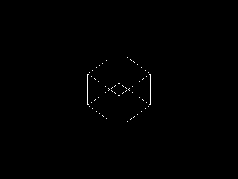
Not a demo pattern for line quality anymore — geometry we care about, projected onto the framebuffer.
Let’s talk about projections first.
What orthographic projection is
Until now we drew directly in screen space: endpoints were already pixel coordinates. This milestone is the first time we place geometry in 3D world space and need a deliberate map from there onto a 2D bitmap.
Why we need projection at all
A rasterizer ultimately writes pixels: a flat grid of (column, row) addresses. Our cube lives in three coordinates per vertex — width, height, and depth in the scene. Something has to answer: given a point in the world, which pixel (if any) should we touch?
That map is projection. In a full renderer it usually sits in a short chain:
- Model — put mesh vertices where the object sits (position, rotation, scale).
- View — express the scene relative to the camera (where the eye is, which way it looks).
- Projection — collapse the remaining depth information into the 2D image plane (orthographic or perspective).
- Viewport — scale and shift into framebuffer pixels (our 800×600 grid, Y flip, aspect correction).
We are only partway into that chain in 0.0.3 — fixed view, minimal projection, viewport math in ortho_camera — but the question is the same: 3D in, 2D out. Without projection, we would have to hand-place every line in pixel space and could not rotate a cube in world coordinates.
In practice the two 3D projection types you meet most often are orthographic (parallel view rays) and perspective (rays through an eye). This milestone uses orthographic; we will add perspective for the cube later.
What orthographic projection does
Orthographic projection is the parallel case.
- Imagine view rays all perpendicular to the image plane — like a very distant viewer where lines of sight never converge.
- A point is projected by sliding it along its ray until it hits the plane. Depth along the view direction does not change where the point lands on the plane — only the position within that plane matters.
Equivalently: drop the coordinate along the view axis and keep the other two. In our conventions (+Z forward, camera looking down +Z), screen position depends on x and y only; moving a vertex forward or backward along z does not slide it left or right or up and down on the image.
That is why orthographic views feel like technical drawings or blueprints: parallel edges in the world stay parallel on screen, and objects do not grow larger when they move closer. Two cubes at different depths but the same (x, y) paint the same pixel. There is no vanishing point and no foreshortening from distance.
Perspective projection does the opposite: rays meet at the eye, distant objects look smaller, and parallel lines (railroad tracks) appear to converge. For now, orthographic matches “true size on the drawing sheet” and keeps the math small while we wire up transforms and tests.
From lines to a scene
The rendering loop stays small. We keep draw_line from 0.0.2; main now owns the scene:
- eight corner vertices in model space (
CUBE_VERTS, edge length 0.5 centered at the origin), - twelve undirected edge pairs (
CUBE_EDGES), - for each edge: rotate the cube, transform both endpoints with
Camera::transform, then rasterize.
draw_cube_wireframe walks that edge list. No triangle fill, no depth buffer — only segments.
We also added glam for Vec3, Mat3, Mat4, and UVec2. The custom Point(u32, u32) wrapper went away; pixel endpoints are glam::UVec2 end to end so types stay consistent as the scene grows.
Why the cube must be tilted
Our 0.0.3 orthographic path ignores z when placing pixels (see below). Without a model rotation, an axis-aligned cube collapses: the front face fills the square, and edges that differ only in z share the same (x, y) — they never show up.
We tried a face-on, axis-aligned pass first to sanity-check aspect ratio (one square on screen — expected). The shipped pose tilts the cube π/4 about Y, then X (Mat3::from_rotation_x * Mat3::from_rotation_y), documented in draw_cube_wireframe. That is enough for depth-only edges to appear while the camera math stays simple.
The camera stays fixed for this release; only the model rotation changes the picture.
Mapping world space to the framebuffer
Module ortho_camera defines a Camera built once per framebuffer size. It maps world coordinates → pixel coordinates under conventions documented in the module: left-handed scene, +Y up, +Z forward, bitmap origin top-left with +y down.
A deliberately simple camera
We are not building a general camera system yet. The scene assumes one fixed pose, aligned with the project spec:
- Eye at (0, 0, −1)
- Look-at the origin (0, 0, 0)
- Up along +Y
One unit back on −Z, looking down +Z, sky in +Y. There is no look_at view matrix in code — with this pose, world x and y feed projection as-is, and z is dropped for screen placement.
Camera::transform still does the framebuffer work: scale (shared factor from the shorter edge, centered), flip y (bitmap rows grow downward), round to integers. The simplification is the fixed camera pose, not skipping viewport math.
We chose that on purpose. Movable eyes, arbitrary targets, and full view matrices are useful later, but they add sign conventions we do not need while learning wireframes. For now: rotate the cube in model space, project xy, draw lines. We may add look_at, orthographic frustum boxes, or a moving viewpoint once the pipeline feels familiar.
Aspect ratio
Early on we hit aspect distortion: mapping [-1, 1]² independently onto 800×600 stretches a world-square into a 4:3 rectangle. The fix uses one scale from the shorter edge, centered:
scale = min(width − 1, height − 1) / 2
px    = world.x * scale + (width − 1) / 2
py    = −world.y * scale + (height − 1) / 2
On a non-square viewport that letterboxes or pillarboxes so equal world spans along x and y occupy equal pixel spans.
Under the hood this is a precomputed Mat4 (ndc_viewport_matrix): homogeneous multiply, then round. Same mapping, clearer composition when we add more matrix stages.
A unit test (world_z_shift_does_not_change_screen_xy) locks in that z does not affect xy pixels yet — no depth buffer in this milestone.
How we got here
Between 0.0.2 and 0.0.3 we explored orthographic projection the hard way: integration tests, NDC conventions, viewport mapping, even depth packing — then peeled back scope when the milestone picture cleared.
There was briefly a richer stack: mesh modules, triangle soup, wireframe edges from triangulation, look_at_lh, orthographic frustum parameters, fractional line endpoints, a golden WebP with JSON metadata. Sergey kept the tests, planning notes, and reference image, but deleted the implementation and rebuilt step by step rather than inheriting a large diff.
Version 0.0.3 is that slimmer rebuild: cube data in main, projection in ortho_camera, the line rasterizer unchanged. Same diary lesson as before — use agents heavily, but own the code you will maintain six months from now.
Testing the full scene
Line tests still use ASCII art helpers. For the whole image we compare decoded RGBA bytes against a committed snapshot at snapshots/cube/scene.webp.
Regenerate after intentional visual changes:
cargo run --quiet -- snapshots/cube/scene.webp
Two levels of feedback again: local geometry in unit tests, pixel-exact scene stability at integration scope.
What this version unlocks
We now have the orthographic wireframe backbone from the milestone breakdown: fixed camera, twelve edges, one model orientation, still image only.
Not in 0.0.3 yet: animation, perspective, filled triangles, depth buffer, culling, or lighting.
Next up was animated orthographic wireframe — the cube starts spinning in the follow-up post. After that: perspective, then filled raster with depth.